Download Code
Consider a rotor rotating around a fixed axis. Because of wear and damage, the mass distribution is not homogeneous. This leads to dangerous vibrations in the rotation. A prototypical example can be a wind turbine, affected by misalignment of the blades and/or mass imbalance of the hub and blades [2].
In order to compensate the imbalance, two balancing heads are mounted at the endpoints of the axle, as in figure 1. Each balancing head is made of two masses free to rotate.
Our goal is to determine the optimal movement of the balancing masses to minimize the vibrations. Control theoretical techniques are employed. For further details, see [6].
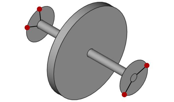
Figure 1: representation of the rotor and the balancing. The balancing heads are located at the endpoints of the spindle. The four balancing masses (two for each balancing head) are drawn in red.
Consider a rotor-fixed reference frame $(O;(x,y,z))$. Figures 1 and 2 show a front view of the device and a scheme of the balancing heads.
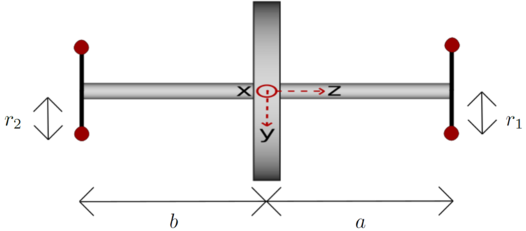
Figure 2: front view of the system made of rotor and balancing device.
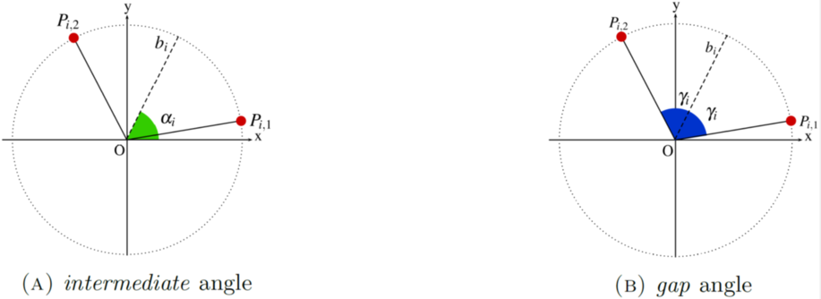
Figure 3: scheme of one balancing head. The balancing masses $(m_i,P_{i,1})$ and $(m_i,P_{i,2})$ are drawn in red. The bisector of the angle generated by $\overset{\longrightarrow}{OP_{i,1}}$ and $\overset{\longrightarrow}{OP_{i,2}}$ is the dashed line. The *intermediate* angle $\alpha_i$ is represented in 3(A), while the *gap* angle $\gamma_i$ is depicted in 3(B). The angles $\alpha_i$ and $\gamma_i$ give the position of the balancing masses in each balancing head.
We consider two planes
orthogonal to the rotation axis $z$. The balancing device (see figures 1 and 2) is made of two heads lying in each of these planes.
The heads are fixed to the rotor and rotate with it. In particular, $\alpha_i$ and $\gamma_i$ are defined with respect to the rotor-fixed reference frame $(O;(x,y,z))$.
Each head is made of a pair of balancing masses, which are free to rotate orthogonally to the rotation axis $z$.
Namely, we have
- two mass-points $(m_1,P_{1,1})$ and $(m_1,P_{1,2})$ lying on $\pi_1$ at distance $r_1$ from the axis $z$, i.e., in the reference frame $(O;(x,y,z))$
- two mass-points $(m_2,P_{2,1})$ and $(m_2,P_{2,2})$ lying on $\pi_2$ at distance $r_2$ from the axis $z$, namely, in the reference frame $(O;(x,y,z))$
For any $i=1,2$, let $b_i$ be the bisector of the angle generated by $\overset{\longrightarrow}{OP_{i,1}}$ and $\overset{\longrightarrow}{OP_{i,2}}$ (see figure 3). The intermediate angle $\alpha_i$ is the angle between the $x$-axis and the bisector $b_i$, while the gap angle $\gamma_i$ is the angle between $\overset{\longrightarrow}{OP_{i,1}}$ and the bisector $b_i$.
The imbalance is modelled by a resulting force $F$ and a momentum $N$ orthogonal to the rotation axis. In the rotor-fixed reference frame $(O;(x,y,z))$, set $P_1 := (0,0,-a)$, $P_2 := (0,0,b)$, $F := (F_x,F_y,0)$ and $N := (N_x,N_y,0)$. By imposing the equilibrium condition on forces and momenta, the force $F$ and the momentum $N$ can be decomposed into a force $F_1$ exerted at $P_1$ contained in plane $\pi_1$ and a force $F_2$ exerted at $P_2$ contained in $\pi_2$.
In each plane, we generate a force to balance the system, by moving the balancing masses:
- in the plane $\pi_1$, we compensate $F_1$ by the centrifugal force:
- in the plane $\pi_2$, we compensate $F_2$ by the centrifugal force:
The overall imbalance of the system is then given by the resulting forces in $\pi_1$ and $\pi_2$,
and
respectively.
The overall imbalance on the system made of rotor and balancing device is measured by the imbalance indicator
Our task is to find a control strategy such that
- the balancing masses move from their initial configuration $\Phi_0$ to a final configuration $\overline{\Phi}$, where the imbalance is compensated;
- the imbalance and velocities should be kept small during the correction process.
We address the minimization problem
where $Q(\Phi) := G(\Phi)-\inf G$ and
with .
The theoretical analysis of the above problem is in [6]. The existence of the optimum is proved. The stabilization of the optimal trajectories towards steady optima is proved in any condition.
Simulation
In order to perform some numerical simulations, we firstly discretize our cost functional and then we run AMPL-IPOpt to minimize the resulting discretized functional.
For the purpose of the numerical simulations, it is convenient to rewrite the cost functional as
subject to the state equation
Discretization
Choose $T$ sufficiently large and $Nt \in \mathbb{N} \setminus {0,1}$. Set
The discretized state is , whereas the discretized control (velocity) is $(\psi_{i})_{i=0, … ,Nt-2}$. The discretized functional then reads as
subject to the state equation
Execution
The discretized minimization problem is
We address the above minimization problem by employing the interior-point optimization routine IPOpt (see [3,4]) coupled with AMPL [1], which serves as modelling language and performs the automatic differentiation. The interested reader is referred to [8, Chapter 9] and [7] for a survey on existing numerical methods to solve an optimal control problem.
In figures 4, 5, 6 and 7, we plot the computed optimal trajectory for \eqref{functional}, with initial datum $\Phi_0=\left(\alpha_{0,1},\gamma_{0,1};\alpha_{0,2},\gamma_{0,2}\right) := \left(2.6,0.6, 2.5,1.5\right)$. We choose $F$, $N$ and $m_i$. The exponential stabilization proved in [6] emerges.
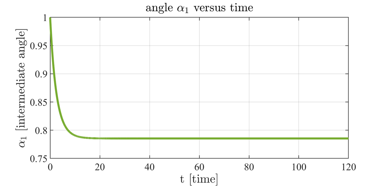
Figure 4: intermediate angle $\alpha_1$ versus time.

Figure 5: gap angle $\gamma_1$ versus time.
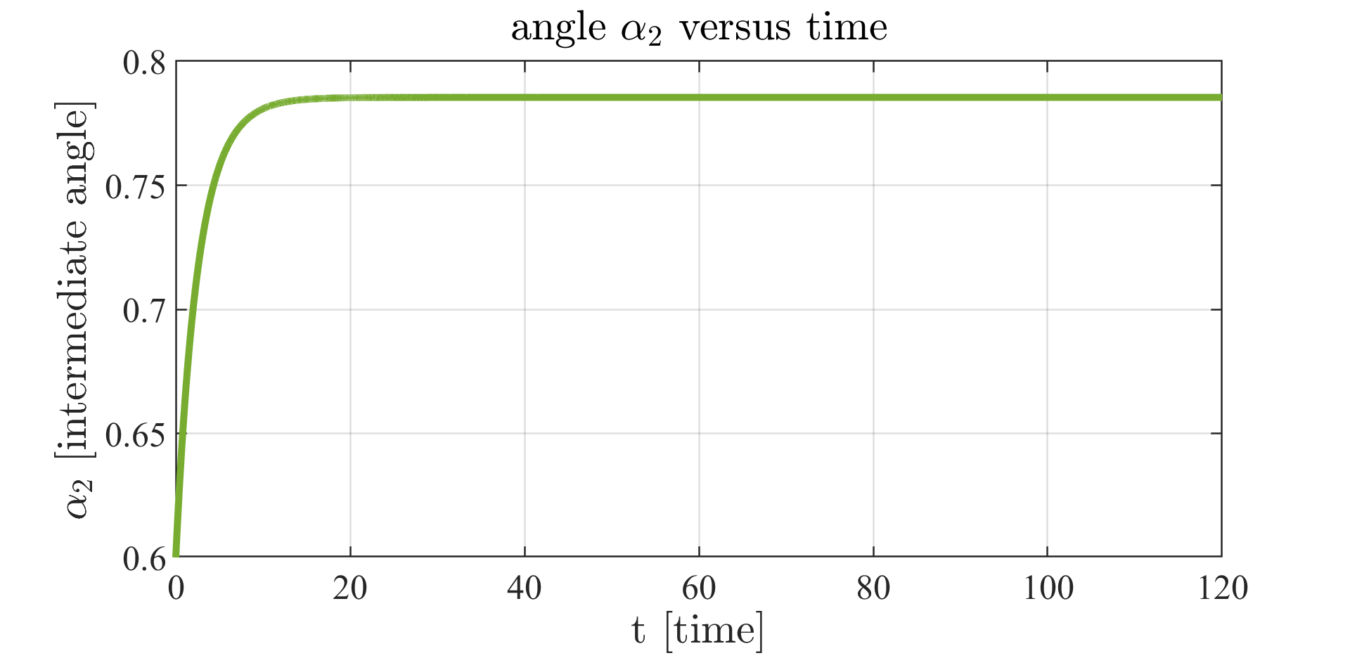
Figure 6: intermediate angle $\alpha_2$ versus time.
In figure 8, we depict the imbalance indicator versus time along the computed trajectories. As expected, it decays to zero exponentially.
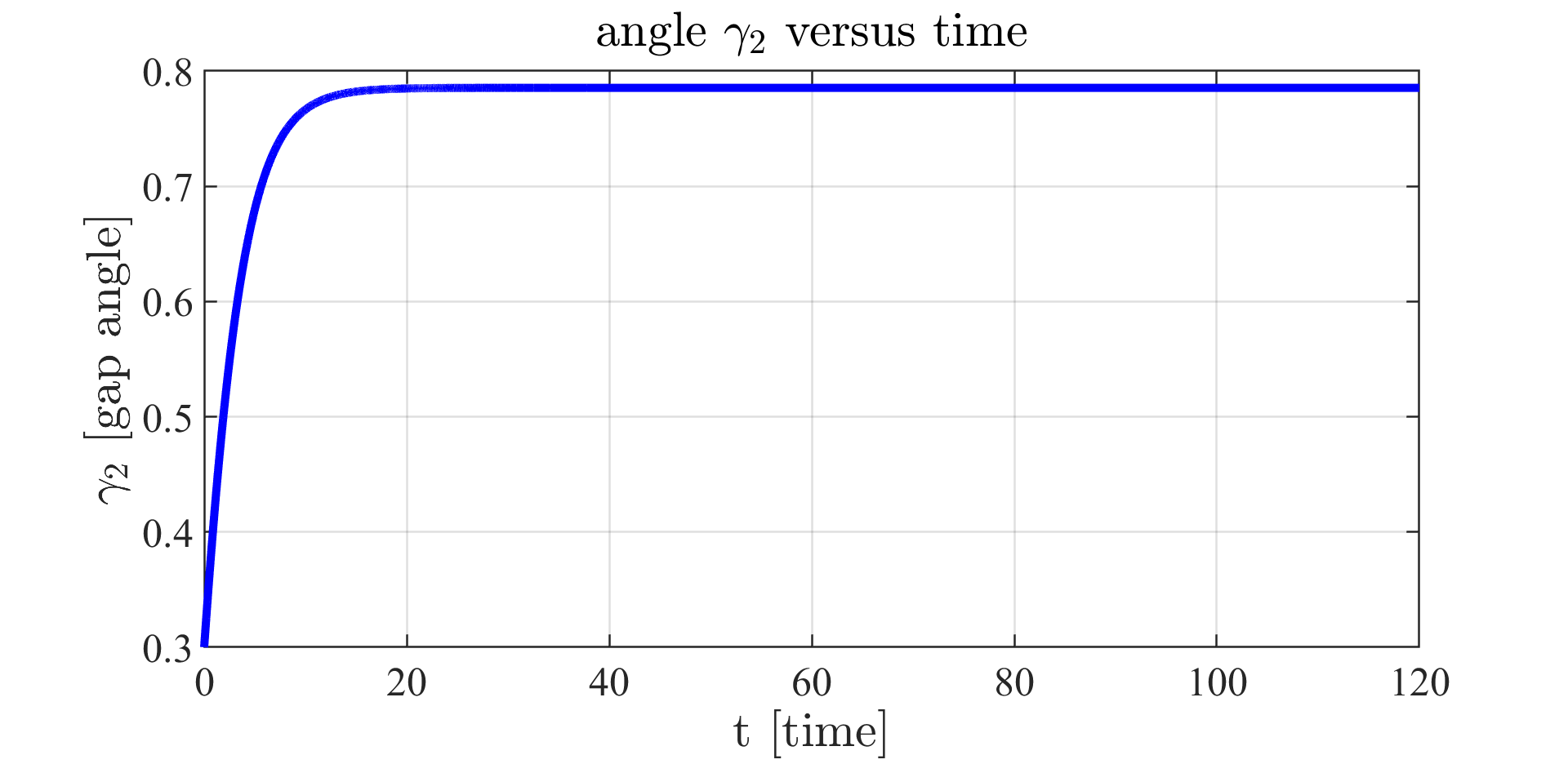
Figure 7: gap angle $\gamma_2$ versus time.
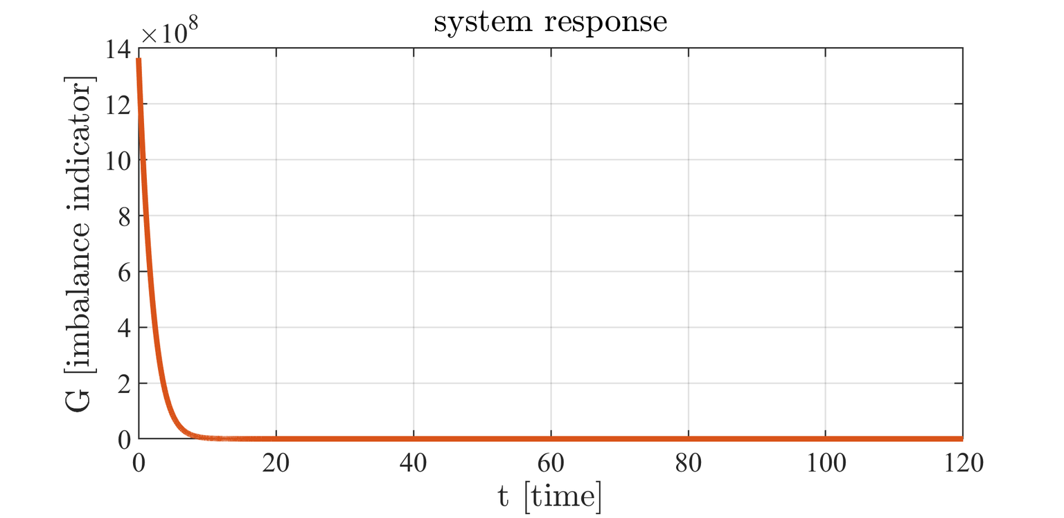
Figure 8: system response.
Figure 9: We represent the evolution in time of the rotor vibrations.
In the uncontrolled case, the balancing device does not act. In the controlled case, our balancing strategy suppress the vibrations.
References:
[1] Robert Fourer, David M Gay, and Brian W Kernighan. A modeling language for mathematical programming. Management Science, 36(5):519{554, 1990.
[2] Mike Jeffrey, Michael Melsheimer, and Jan Liersch. Method and system for determining an imbalance of a wind turbine rotor, September 11 2012. US Patent 8,261,599.
[3] Andreas Waechter, Carl Laird, F Margot, and Y Kawajir. Introduction to ipopt: A tutorial for downloading, installing, and using ipopt. Revision, 2009.
[4] Andreas Waechter and Lorenz T Biegler. On the implementation of an interior-point �lterline-search algorithm for large-scale nonlinear programming. Mathematical programming, 106(1):25{57, 2006.
[6] Matteo Gnuffi, Dario Pighin and Noboru Sakamoto. Rotors imbalance suppression by optimal control. Preprint.
[7] Noboru Sakamoto and Arjan J van der Schaft. Analytical approximation methods for the stabilizing solution of the Hamilton-Jacobi equation. IEEE Transactions on Automatic Control, 53(10):2335{2350, 2008.
[8] Emmanuel Trélat. Contrôle optimal : théorie et applications
Mathématiques Concrètes. Vuibert, Paris, 2005. available
online:
https://www.ljll.math.upmc.fr/trelat/�chiers/livreopt2.pdf.